It all seems so simple. Drive up; plug in; swipe an app or tap your credit card/RFID key, and hey-presto, you’re charging up your EV. And for those of you rolling your eyes about the last failed charging experience you had, let’s remember that the vast majority of EV charging attempts do succeed. Yes, we frown upon success rates of 80%, and we all want that to improve, but if you ever considered everything that happens behind the scenes of an EV charging session, you might be a bit more forgiving. That’s exactly what this post is about. Let’s dig into some details.
EV charging flow
While there are variations in how an EV charging session is conducted (for example, how the charging session is initiated – whether by tapping a credit card at a payment terminal, or by swiping a button on an app), the following sequence summarizes the main steps. We’ll consider an AC charging session over a CCS connection for our example. Each of these steps is governed by industry standards without which every EV would be limited to a handful of compatible chargers; not a commercially viable situation.
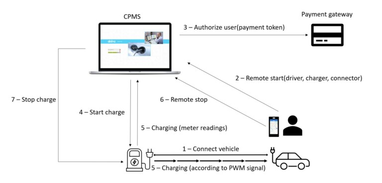
A typical EV charging sequence
For a charging sequence to proceed according to a set protocol, the EVSE (Electric Vehicle Supply Equipment, i.e., the charging station) must be able to communicate with the vehicle once it’s connected. Since CCS is an extension of Type 1/Type 2, basic communication is done using Pulse Width Modulation (PWM) through the connector’s Control Pilot (CP) pin as specified in IEC 61851-1.

1. Connect vehicle
The session is initiated when the driver plugs the cable into the vehicle. IEC 61851-1 describes 6 states that an EV can be in during a charging cycle.
| State | Charging Status |
| A | Standby |
| B | Vehicle detected |
| C | Ready for charging (ventilation not required) * |
| D | Ready for charging (ventilation required) |
| E | EVSE shut off |
| F | Error |
*If ventilation is required, the EVSE will only supply charging power if the area is ventilated (i.e., outdoors)
Initially, the vehicle is not connected, in state A – Standby. The voltage detected at the CP is a steady 12V signal. When the driver connects the cable, the EVSE drops the voltage at the CP to 9V to indicate a good connection and we are in state B. The EVSE changes the signal at the CP to a PWM signal alternating between -12V and +12V. The duty cycle of the pulse notifies the vehicle of the maximum current available for charging. For example, a 10% duty cycle indicates 6A are available, while 96% duty cycle indicates 65A are available. In some vehicles, different components communicate with each other over a Local Internet Network (LIN), and the EVSE communicates with the vehicle over a Single Wire Controller Area Network (SWCAN). In these cases, the duty cycle on the CP is between 3 – 7%, and the additional communication capabilities enable the vehicle to provide the EV with information such as State of Charge (SOC and State of Health (SOH). A DC charging session enables an even greater range of options since the connection is directly to the vehicle’s BUS.
The vast majority of failed EV charging sessions today happen because of an issue that arises in this step causing either charger or the vehicle to reject the charging session. For example, a vehicle may reject a charger because of a bad connection caused by a grounding problem with the cable. On the flip side, a problem with firmware can cause a charger to refuse a connection. Connecting and reconnecting the vehicle can often fix the issue. Many such issues generate error codes which the CPMS managing the chargers can capture. Based on these error codes, advanced CPMSs can run self-healing algorithms that resolve different issues remotely and automatically, often, without requiring any down-time of the charger, averting failed charging sessions in the future. There can also be issues, especially in roaming scenarios, or in areas of poor cellular coverage, that experience as much as a 2-minute lag a step in the communications protocols causing a session to time out.
2. Remote start
After the driver connects the cable, he swipes the arrow on the app to start charging. Note that the driver has logged into the app with a username and password and is, therefore, considered authenticated.
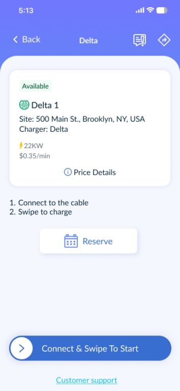
The app sends a remote start request to the associated CPMS providing parameters such as the charger id, the connector id and the user’s id.
3. Authorize user
When the user registered for the EV charging service, he provided payment information which the CPMS approved with the corresponding payment gateway. While the CPMS does not store the user’s credit card data, it does store an identification token provided by the payment gateway in the driver’s account. When the app sends the remote start request with the driver’s identifier, the CPMS extracts the corresponding payment token and sends an authorization request to the payment gateway. If the user has the required minimum credit available defined by the CPMS, the payment gateway authorizes the user.
4. Start charge
This is where OCPP kicks in. Once the user has been authorized, the CPMS sends an OCPP StartTransaction request to the corresponding charger which responds to the CPMS with a confirmation. The charger then drops the CP voltage to 6V to indicate to the vehicle that it is ready for charging (state C or D depending on whether the vehicle has indicated it requires ventilated charging or not)
5. Charging
Once the charger has indicated to the EV that it is ready for charging, and the amount of current available, the EV starts to draw energy. During the charging process, the charger sends periodic meter readings to the CPMS over OCPP indicating the amount of energy delivered to the vehicle. At the same time, the charger may receive requests by the CPMS to increase or decrease the available current for charging. Such requests may originate from the grid as a means to reduce consumption, or as a load balancing maneuver initiated by the CPMS. In turn. the charger notifies the vehicle by changing the duty cycle of the PWM signals on the CP, and the vehicle will change its energy consumption accordingly.
6. Remote stop
When the user is ready, he will swipe the app to stop charging. This sends a remote stop request to the CPMS.
7. Stop charging
Upon receiving the remote stop request, the CPMS sends a StopTransaction request to the charger over OCPP with the user’s ID. Recognizing that the user is the same one that started the charging session, the charger responds to the CPMS with a final meter reading and stops delivering energy to the vehicle, which is now in state B. The CPMS can now add up the accumulated meter readings for the charging session, access the payment gateway to take payment and issue the driver with an invoice (which the driver can access through his account with the service provider).
At this point, the vehicle is back in State B, meaning that it is connected to the charger, ready to start another charging sessions, but the connector is not locked and can be removed by the driver who can now move on to his next destination. Naturally, when the connector is removed, the CP line goes back to 12V.
In practice, this is still a simplified view of the process. For example, the different PWM signals over the CP are not always precise and must remain within specified levels of tolerance. Any deviation from those levels can prevent the vehicle from moving to the right state in the sequence and cause an error. There may be glitches in the cellular network that hinder correct communication between the charging app and the CPMS, or between the CPMS and the EVSE. There can even be mechanical malfunctions in the mechanism that locks the connector to the vehicle. Let’s also remember that an EVSE is a complex piece of apparatus that can malfunction in any number of places. There are thousands of vendors manufacturing thousands of charger models, each of which may have its quirks. In many cases, the CPMS can remotely and automatically detect and fix malfunctions in chargers using self-healing algorithms (all communicated to the charger over OCPP). And yet, the industry is still at a level of maturity in which most of us have experienced failed attempts to charge. At least now, you have some idea of why that sometimes happens.